 National Nuclear Regulator Act, 1999
R 385
Occupational Health and Safety Act, 1993 (Act No. 85 of 1993)RegulationsExplosives Regulations, 2024Radio Frequency Device Guidelines7. Examples determining Exclusion Distances |
| 7.1 | Example 1 Intentional transmitter |
Assume as an example that a Motorola GM 644 mobile radio 403 – 470 MHz, 4 W (on Motorola website) is to be used in a danger area.
This is an intentional transmitter because it uses RF for functioning i.e. communication.
Then in Government Gazette No. 38641 of 30 March 2015, Annexure B, nearest frequencies 446 - 446.1 MHz, gives a Public mobile radio (PMR), 500 mW EN 300 296 following 12,5 kHz eight channels spacing, but no ERP i.e. no restriction. In Annexure I, 430 -440 MHz, gives Coprimary A = 30 dBW, B = 20 dBW. However, this is for an unlicensed transmitter (less than 1W). Since the Motorola is 4W, an application must be done for a licence.
Using the exclusion distance graph in Figure 3, the exclusion distances are read off for an Effective Radiated Power = 4W as follows:
For 10 V/m exclusion distance is 1,3 m
For 3 V/m exclusion distance is 4,5 m
For 1 V/m exclusion distance is 10,3 m
| 7.2 | Example 2 Unintentional transmitter |
Assume as an example that a CCTV camera will be installed on an assembly line hard wired to the PC in the control room to monitor the coiling of shock tubes.
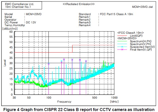
The camera has a CE mark. So, the supplier was asked for the CISPR 32 (Commercial) or CISPR 11 (Industrial) reports. Data sheet for camera states EMC compliance with CISPR 32 Class B, which gives from Figure 4 below a maximum effective radiated power of 34 dBμV/m.

The above graph shows that the radiated power of the camera (34 dBμV/m) is far below 1 V/m and therefore an exclusion distance of 0 can be adopted i.e. no exclusion distance.
| 7.3 | Example 3 Intentional transmitter |
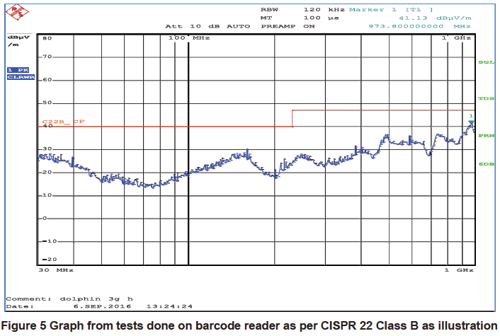
Assume as another example that an induction RF barcode reader is installed on an electric detonator assembly line to weld wires to fuse heads. There is no CE mark on the barcode reader. Therefore, arrange for an EMC laboratory to carry out testing or calculations to determine the Effective Radiated Power of the barcode reader. As illustration, after test carried out on the barcode reader the EMC laboratory produced test results as per graph in Figure 5 below. This shows that the maximum emitted field strength (40 dBμV/m) is far below 1V/m and hence no exclusion distance will apply.

| 7.4 | Applying the exclusion distance formulas |
Referring to Example 3, noting that the tested maximum field strength of the RF barcode reader was determined as 40 dBμV/m at a 3m test distance.
Calculating the field strength Erms in linear terms from the logarithmic value (maximum field strength) on the graph as:

The effective radiated power in Watts from the barcode reader is then calculated from equation 5 as:
![]()
where: E is the field strength (Erms) calculated from the information from the graph using the relationship above in volts per metre and R is the test distance from the barcode reader metres
The ERP of the barcode reader based on the 40dBuV/m indicated in the graph is therefore:

using equation 3, exclusion distance is calculated as:

| Where | P= barcode reader ERP (W) |
Ecrit = susceptibility level of equipment (assumed to be 1V/m worst case) (V/m)
This confirms a zero-exclusion distance.
| 7.5 | Procedure determining separation of susceptible equipment from transmitters |
| (i) | Select the process control equipment e.g. temperature transmitters, PLC, proximity switches etc. |
| (ii) | Confirm whether the equipment has a |
| (iii) | Determine the susceptible field strength of the equipment i.e. in V/m from suppliers’ specifications |
| (iv) | Compare the susceptible field strength above in (iii) with the separation distance determined for intentional and un-intentional transmitters |
| (v) | Finally specify the required separation distance, for the various process control equipment |
| 7.6 | Procedure for determining separation of susceptible explosives |
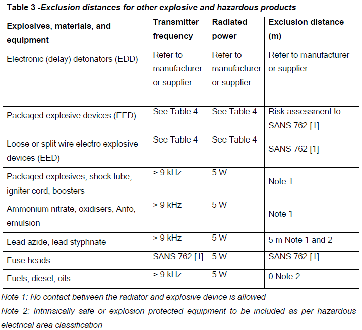
| (i) | Select the explosives and devices e.g. emulsion, electro explosive device, fuse head etc. (see Table 3). |
| (ii) | Confirm whether the equipment has complied with a test standard. |
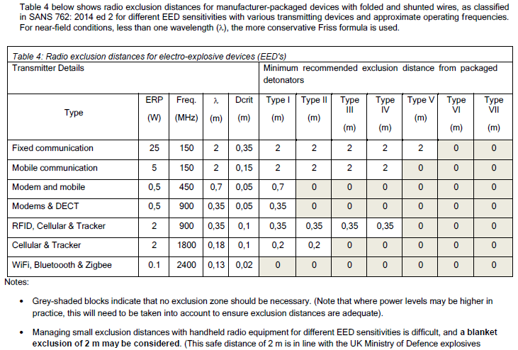
| (iii) | Determine the susceptible field strength of the explosives i.e. in V/m from suppliers’ specifications (see Table 4 for packaged EED, otherwise refer to supplier). |
| (iv) | Compare the susceptible field strength above in (iii) with the separation distance determined for intentional and unintentional transmitters. |
| (v) | Finally specify the required separation distance, for the various explosives. |


